Exercise 3 - Computer Vision for Robotics
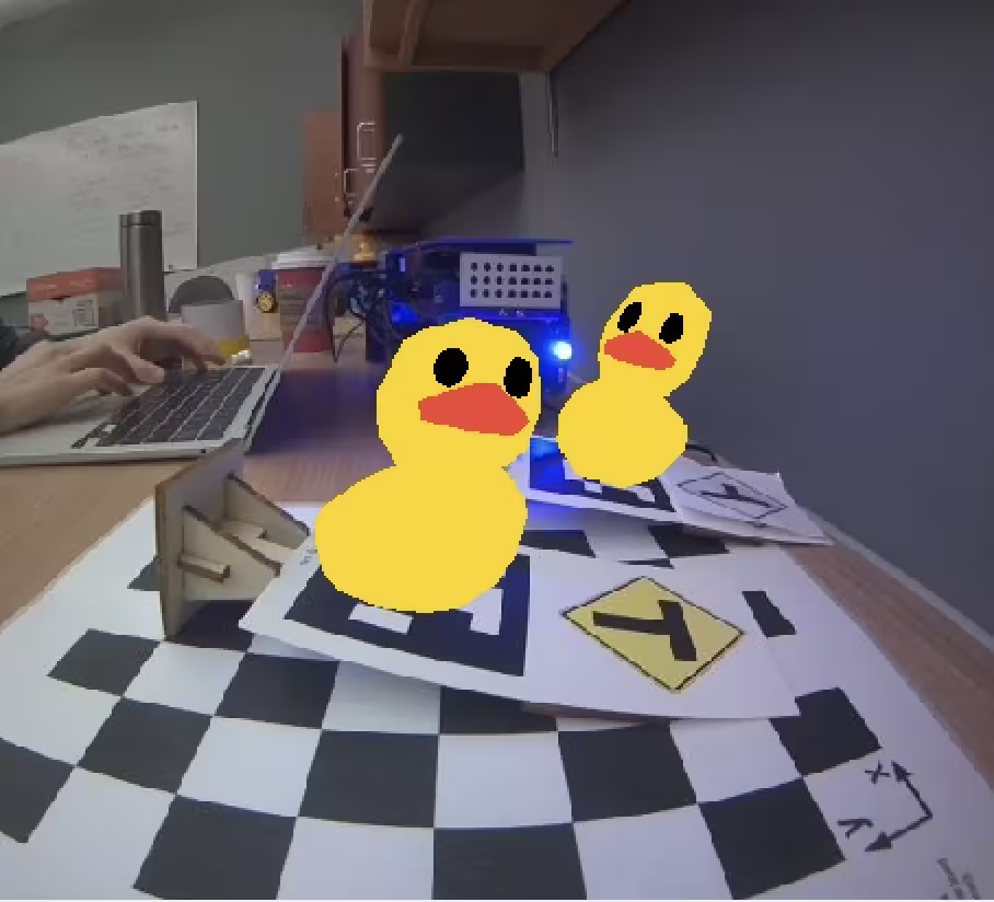
A screenshot of our Unit A-4 Advanced Augmented Reality Exercise results.
Part One - Computer Vision
Deliverable 1: April Tag Detection and Labeling
The following video depicts our apriltag detector image topic viewed with
rqt_image_view demonstrating our apriltag node detecting several apriltags and
labeling each with its bounding box and ID number.
What does the april tag library return to you for determining its position?
The april tag library returns pose_R with shape (3, 3) which is the rotation
matrix and pose_t with shape (3,) which is a translation vector of the
april tag in the camera_optical_frame frame.
Which directions do the X, Y, Z values of your detection increase / decrease?
X corresponds to the horizontal translation of the april tag relative to the camera,
it increases when the april tag is moved towards the right of the camera and
decreases when the april tag is moved towards the left of the camera.
Y corresponds to the vertical translation of the april tag relative to the camera,
it increases when the april tag is moved above the camera and
decreases when the april tag is moved below the camera.
Z corresponds to the depth of the april tag relative to the camera, it
increases when the april tag is moved further from the camera and decreases
when the april tag is moved closer the camera.
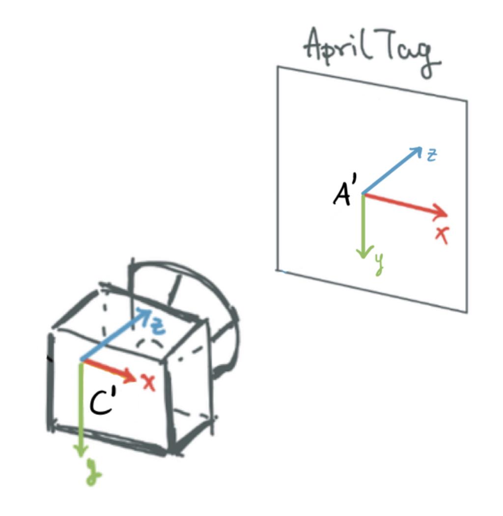
What frame orientation does the april tag use?
The april tag frame is centered at the center of the tag, with the direction of the positive x-axis towards the right of the tag, the direction of the positive y-axis towards the tag.
This is nicely visualized in this diagram from Figure 4.4 of Unit B-4 Exercises - state estimation and sensor fusion in the Duckmentation.
Why are detections from far away prone to error?
Far away april tags have fewer pixels to detect, so they are more prone to error in their pose estimations and unstable detection as can be seen in the video with apriltag ID 94.
Why may you want to limit the rate of detections?
April tag detection is computationally expensive, so limiting the rate of detections can reduce Duckiebot CPU usage. Furthermore, if the image does not change much, it is can unnecessary to recompute April tag detections.
Learnings
From looking at the camera_driver source code, I learned that we can use cv_bridge
to convert between OpenCV images and CompressedImage messages
The image_geometry package was useful for undistorting raw images using the intrinsics calibrations.
Challenges
The template-ros repository has a .dockerignore and it ignores our
additional files and directories, we have to whitelist them like:
!maps
After upgrading to Docker 23.0.1, dts devel run would error with message:
docker: Error response from daemon: No command specified..
I had to downgrade to Docker 20.10.23 to get it to work again.
export VERSION_STRING=5:20.10.23~3-0~ubuntu-focal
sudo apt-get install docker-ce=$VERSION_STRING docker-ce-cli=$VERSION_STRING containerd.io docker-buildx-plugin docker-compose-plugin
Part Two - Lane Following
Deliverable 2: Lane Following English Driver Style
This video has our bot complete a full map with the English-driver style
The English-driver was implemented with a P-controller and drives on the left.
Here are some videos for other driving styles we implemented:
- American driver. 0.3 velocity, P-controller, drives on the right
- Drunk driver. 0.6 velocity, P-controller, attempts to drive on the left
What is the error for your PID controller?
We use a multi-stage Opencv pipeline to process the image
- Crop out the top
1/3and bottom1/5. - Blur the entire image by 5 pixels in both directions
- Apply HSV thresholds to mask out everything except the dashed yellow line.
We have two separate thresholds, one for each room. Both thresholds mask out
ducks, though the
csc229one doesn’t correctly mask out the carpet incsc235. - Detect contours in the new black-white image
- Sort contours by area. We initially considered using the top-k contours and averaging them, though we found outlier contours can do a lot more damage this way, so we just used the single largest one instead
- Find the center of the largest contour
- Draw a line from the center of the largest contour to the right (left with English-driving) with a length of exactly the distance of the center point from the top of the image
- Set the error as the signed difference between x-coordinate of the line’s right-most point and the x-coordinate of the center of the image. This means the error is measured in pixels.
If your proportional controller did not work well alone, what could have caused this?
Initially, our controller failed to work since we processed the images at 3 Hz. The logic is that OpenCV is a “heavy” process, so processing at a high frequency would just lead to pose calculations going into a queue. The system suddenly started working, when we change this to 30 Hz at 0.3 velocity.
However, at 0.6 velocity, the P-term-only controller really struggled (see Drunk driver video). Our P-term-only controller made the English driver look more like the drunk driver. It didn’t work well since a P term fails to consider the momentum built up by the system. At 0.3 velocity, there isn’t enough momentum to effect our controller noticeably. However, at 0.6 velocity this momentum leads to noticeable oscillation and hard turning overshoots.
Does the D term help your controller logic? Why or why not?
The D term was pointless at 0.3. Actually it was detrimental, since the logic of the program got harder to debug. We did try to implement one when using 0.6 velocity, however with 2 minute build times, we weren’t able to sufficiently tune it. An untuned D-term was far worse than a tuned P-controller, mostly since it kept fighting against itself on the turns, which made it end up off the track.
(Optional) Why or why not was the I term useful for your robot?
Given how problematic the D-term was, we never even considered adding an I-term during this assignment. We doubt it’d be much help either, since there isn’t any steady-state error to correct against with an integral term when we’re just driving on a horizontal surface.
Part Three - Localization using Sensor Fusion
Deliverable 3: Record a video on your computer showing RViz: displaying your camera feed, odometry frame and static apriltag frames as it completes one circle. You can drive using manual control or lane following.
Here’s a video of RViz with our Duckiebot driving in a circle. We observe that while at first dead reckoning is reasonable for predictions. However, after a few turns the position estimated using the wheel encoders drifts significantly from the actual position of the robot.
Where did your odometry seem to drift the most? Why would that be?
Most of the drifting occurs as a result of turning the Duckiebot. We learned in class that turns introduce much more uncertainty than forward driving, as turns involve more slippage which makes the dead reckoning angle inaccurate. A slightly inaccurate angle quickly results in the error in the odometry compounding quickly, as dead reckoning integrates the errors over time.
Did adding the landmarks make it easier to understand where and when the odometry drifted?
Yes, quite a bit. Especially at areas that are dense with landmarks, like the intersections, we’re able to really quickly tell how far the duckiebot has drifted. In our video this particularly shows itself around the middle, when the bot is an entire intersection ahead of where Rviz seems to show it.
Deliverable 4: Attach the generated transform tree graph, what is the root/parent frame?
It is quite the big graph, if you need to zoom in, click
here to open the generated
transform tree graph. The root of this tree is
csc22927/footprint.
Move the wheels and make note of which joint is moving, what type of joint is this?
The moving joints are named: csc22927_left_wheel_axis_to_left_wheel and
csc22927_left_wheel_axis_to_right_wheel. The type of joint is continuous, as
seen in this
urdf.
This joint type makes sense as a wheel can
be thought of as a continuous hinge joint that rotates around its axis with no
bounded limits. The links csc22927/left_wheel and csc22927/right_wheel are
the transformations that visually spins in Rviz.
You may notice that the wheel frames rotate when you rotate the wheels, but the frames never move from the origin? Even if you launch your odometry node the duckiebot’s frames do not move. Why is that?
That’s since our parent frame is the csc22927/footprint frame of reference.
Even if the entire robot and odometry is moving, the relative positions of the
duckiebot’s frames to one another never change from their description in the
URDF file.
The wheels do rotate, since that relative change is related by a transform with respect to the footprint’s frame. The wheel’s rotation isn’t fixed relative to the footprint’s frame on two axes.
What should the translation and rotation be from the odometry child to robot parent frame? In what situation would you have to use something different?
The transformation from the odometry child to robot parent frame is zero rotation, zero translation (written as an identity transformation homogeneous transformation matrix). In other words, our robot parent frame is identical to the odometry child frame. If they weren’t the same, we’d have to actually apply a non-trivial transformation to align their coordinate frames.
After creating this link generate a new transform tree graph. What is the new root/parent frame for your environment?
The world frame is the new root of our environment.
Can a frame have two parents? What is your reasoning for this?
No, it’s called a transform tree graph for a reason. To clarify, it is possible to transform between any two nodes in the same tree graph, though having two parent frames is not possible.
Consider a situation where a frame really is defined by two parents. Say it’s a 4 cm x-translation relative to parent A’s frame and a 2cm x-translation relative to parent B’s frame. This immediately implies parent A’s frame is -2 cm in parent B’s frame. However, since there isn’t any direct dependency between them, it’d be possible to violate this assumption by changing the child’s position relative to the two parent frames in an inconsistent way. To guarantee this correlation, we’d have to express either parent A or B in the other’s frame, which brings us back to 1 parent per node.
Can an environment have more than one parent/root frame?
Yes, unlike the one parent per node requirement in transform trees, having two or more separate trees in the same environment doesn’t create any implicit assumptions, since the trees are completely disjoint. However, by doing so you remove the ability to transform between frames in two different trees.
Deliverable 5: Attach your newly generated transform tree graph, what is the new root/parent frame?
It is quite the big graph, if you need to zoom in, click here to open the newly generated transform tree graph.
The new root/parent is the world frame.
Deliverable 6: Record a short video of your robot moving around the world frame with all the robot frames / URDF attached to your moving odometry frame. Show the apriltag detections topic in your camera feed and visualize the apriltag detections frames in rviz.
How far off are your detections from the static ground truth?
At first it was surprisingly not bad. Up until the third (bottom left) turn, it was within 60 cm of where it really was. However, on that third turn the odometry failed to record the turn as hard as it actually was. This made the estimates extremely far off from that point forward.
What are two factors that could cause this error?
Our detections are quite far off from the ground truth. Two factors that could cause this error are inaccurate odometry from wheel encoders and camera transform errors arising from camera distortion.
Challenges
One challenge we faced was actually trying to get the recording of Rviz. If we start Rviz before our transforms are being broadcast, it just doesn’t see them and there doesn’t seem to be any way to refresh Rviz. If we start it too late, the screen recording starts with the bot having moved for several seconds already.
Our solution to this was pure genius:
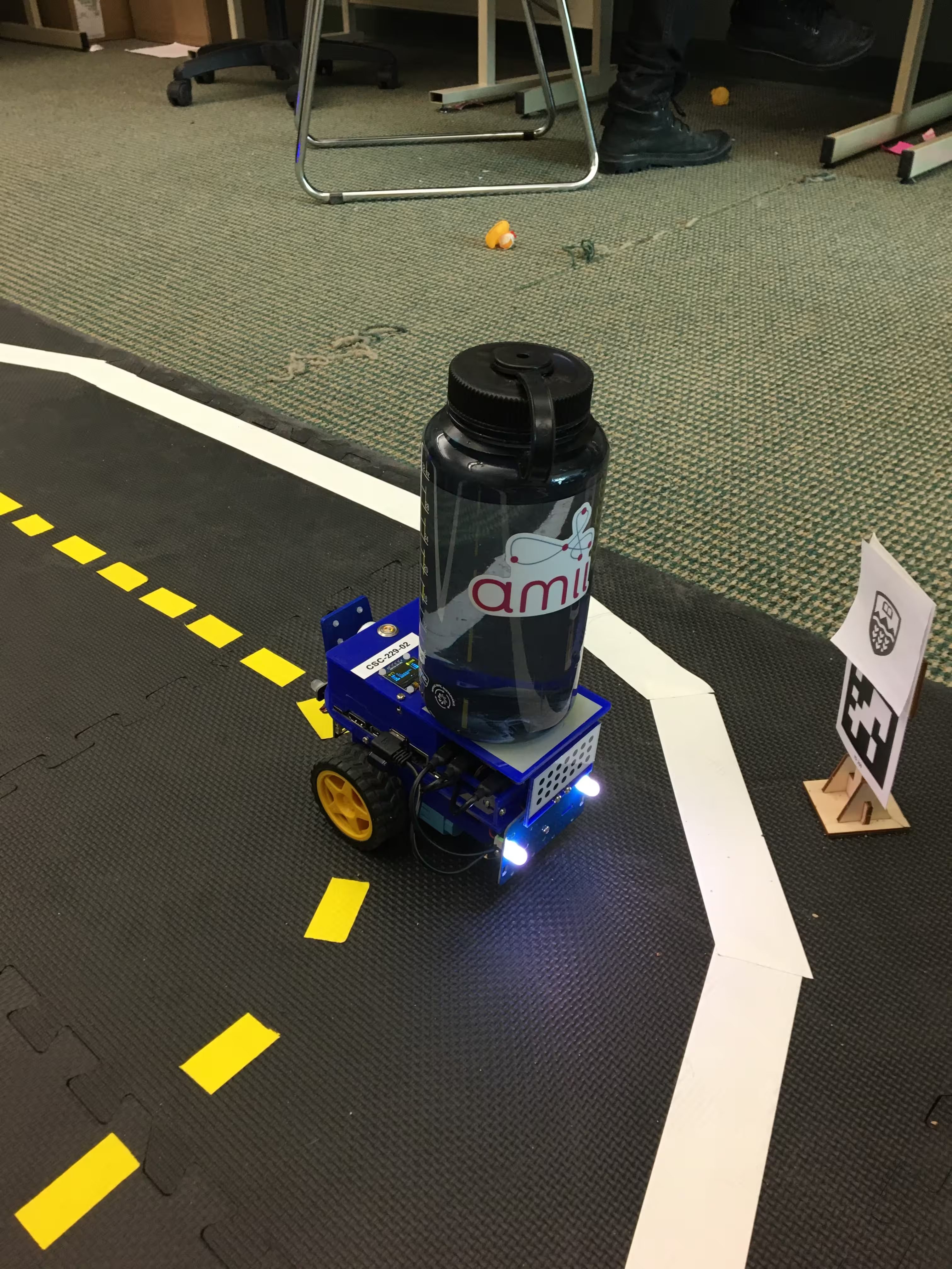
By holding down the bot at the start, the odometry node doesn’t move at all! This gave us the time we needed to startup Rviz, then we just took the bottle off. The videos we present here had that initial ~30 s of just sitting there cropped out.
Another big challenge was the latency introduced by the deadreckoning and
apriltag nodes. When we did part 2, we did it using only the lane-related
nodes, nothing else was running. However, when we enabled our 30 Hz apriltag node and
10Hz deadreckoning node, our lane following code gained about 3 s of latency.
3 s of latency is fatal on a turn, since the lane will go out of frame, so lane
following effectively stopped working.
We fixed this by lowering the apriltag rate to 1 Hz, which is why the video
stream is so much more delayed than the transforms in Rviz, and lowering the
dead reckoning node to 4 Hz. Then it restored its ability to lane follow. We
also turned off the front LEDs to not mess up the lane detector’s color masking,
instead indicating the whole apriltag detection color with the two rear LEDs.
Deliverable 7: Show a short video of your robot moving around the entire world (see image below) using lane following and have your sensor fusion node teleport the robot if an apriltag is found and use odometry if no apriltag is detected. Try to finish as close to your starting point as possible.
We do 3 laps in the video above, to get a better sense of how little it drifts over time. We ended up finishing very close to where we started and much of the error can be attributed to the stochastic city of the lane-finder node, so landmark-based localization was a great help.
Is this a perfect system?
No, while this system is certainly better than dead reckoning, there are still some inaccuracies in our localization. In the video above, we observe errors in localization when our bot sporadically teleports at the top of the map. However, using the fixed landmarks meant that even after 3 laps, it was able to localize itself quite close to its actual position.
What are the causes for some of the errors?
When april tags are far away, the pose estimates are not perfect and can cause our bot to teleport to the wrong place as seen in the video when it only sees tag 200 without tag 201. Latency in the april tag node also causes minor errors when our bot has moved since the detection was made. Sometimes our localization fails right after we turn, as the april tag is no longer visible, and another april tag has not been detected yet. The bot reverts to relying on only dead reckoning, which is especially problematic after turning for reasons described in an earlier question.
What other approaches could you use to improve localization?
We could have tried using multiple april tags (when visible) to improve our localization estimate.
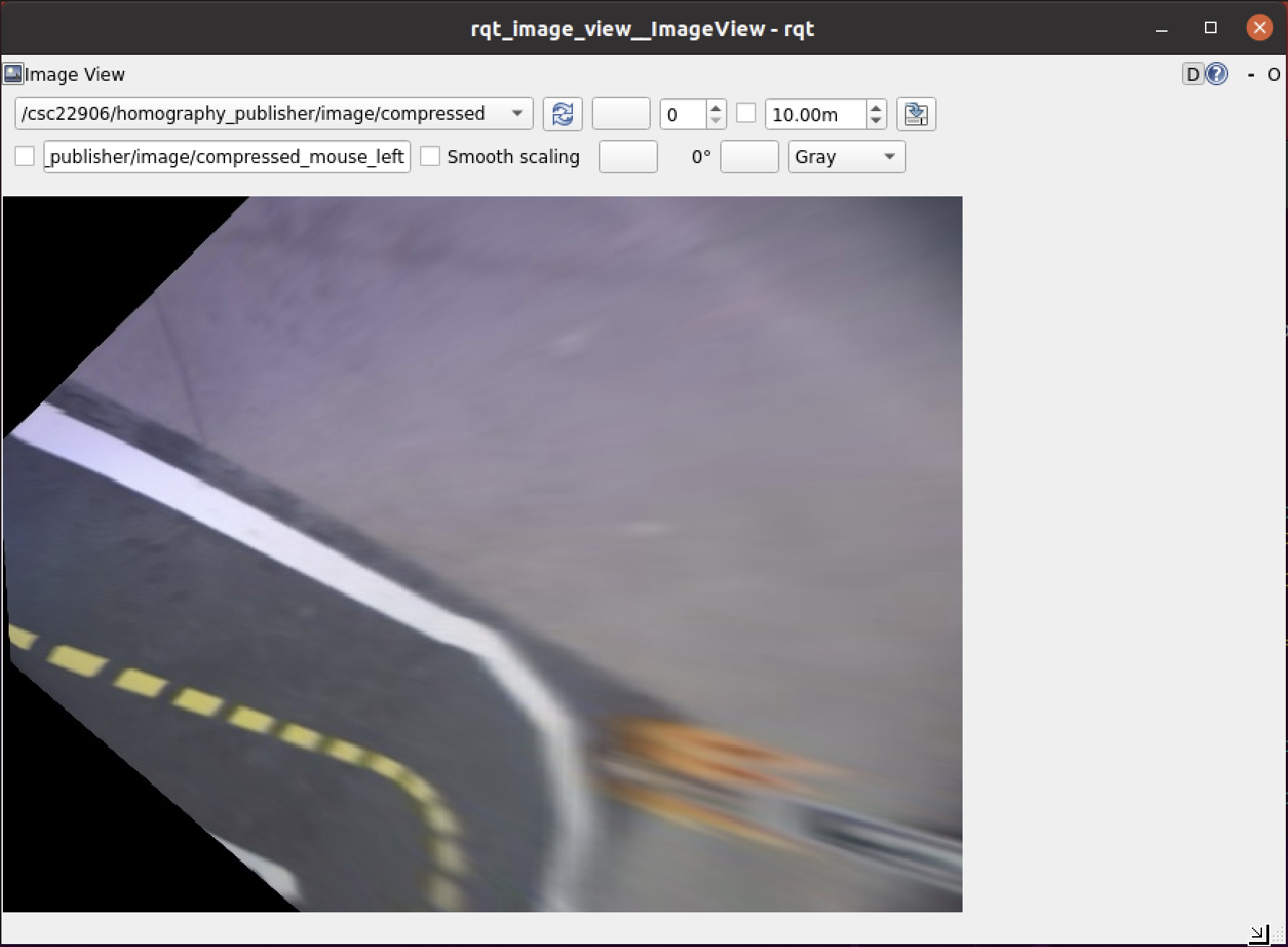 Bird’s eye view obtained using a projective transformation of the image.
Another approach that would address situations where april tags are not visible is that we could use our code that gets a bird’s eye view of the lane markings, fit lines to the lane markings and compare them to a measured ground truth as alternative source of information for localization.
Sources
- https://docs.duckietown.org/daffy/duckietown-classical-robotics/out/cra_basic_augmented_reality_exercise.html
- http://wiki.ros.org/cv_bridge/Tutorials/ConvertingBetweenROSImagesAndOpenCVImagesPython
- https://github.com/duckietown/dt-duckiebot-interface/blob/daffy/packages/camera_driver/
- https://docs.ros.org/en/api/image_geometry/html/python/
- https://docs.docker.com/engine/install/ubuntu/
- https://github.com/duckietown/dt-core/blob/daffy/packages/complete_image_pipeline/include/image_processing/ground_projection_geometry.py#L161
- https://bitesofcode.wordpress.com/2018/09/16/augmented-reality-with-python-and-opencv-part-2/
- https://einsteiniumstudios.com/beaglebone-opencv-line-following-robot.html
- http://wiki.ros.org/tf2/Tutorials/Writing%20a%20tf2%20static%20broadcaster%20%28Python%29
- https://nikolasent.github.io/opencv/2017/05/07/Bird's-Eye-View-Transformation.html
- http://wiki.ros.org/urdf/XML/joint
- https://github.com/duckietown/dt-duckiebot-interface/blob/daffy/packages/duckiebot_interface/urdf/duckiebot.urdf.xacro#L107
- https://wiki.ros.org/tf2/Tutorials/Writing%20a%20tf2%20listener%20(Python)
- https://github.com/AprilRobotics/apriltag/wiki/AprilTag-User-Guide